Torreta controlada por cámara Pixy CMUCam5/ Rotary turret with Pixy CMUCam5

Este proyecto es la copia de otro que vi en youtube, El original está hecho en aluminio para un rifle AR15, como yo no tengo armas reales ni tengo intención de tenerlas lo hice en MDF para una pistola de aire comprimido, la cosa era probar que lo podía hacer. El diseño es mi variante y la programación también. La torreta es guiada automáticamente por colores gracias a una cámara Pixy CMUCam5 que es capaz de seguir hasta 10 colores distintos que se programan. La gracia es que el programa está en la cámara por lo que funciona sin computador y se conecta a un arduino Nano para controlar los motores paso a paso. Al igual que el proyecto original no dispara automáticamente. Próximo paso usar una cámara que detecte movimiento y claro.. dominar el mundo…

This project is a copy of another that I found on youtube, The Original is made of aluminum for an AR15 rifle, as I have no actual weapons or intend to have them I made it in MDF for an airgun, the thing was to prove that I could do it. This is my own design and programming. The turret is guided by colors automatically with a camera Pixy CMUCam5  camera that Is able to track up to 10 colors that are programmed. The program is in the camera so it works without a computer and connects to an Arduino Nano to controlling stepper motors. Like the original project it does not fire automatically. Next step is use a camera with motion detection.

Camera Slider

Este es el último proyecto en el que he estado trabajando un slider para la nueva cámara que compré.

This is the last project I’ve been working a slider for the new camera I bought.

slider2

El slider está hecho de tubos de aluminio, madera terciada y unas poleas torneadas en polietileno montadas en rodamientos.

The slider is made of aluminum tubes, plywood and polyethylene turned pulleys mounted on bearings.

slider9

Las poleas están hecha en polietileno de alta densidad HDPE.
The pulleys are made in high density polyethylene HDPE.
slider11

Luego las poleas se montan sobre rodamientos de 22mm de diámetro.
Then the pulleys are mounted on bearings 22 mm in diameter.
slider12

Hice una herramienta especial para tornear la ranura de las poleas.
I made a special tool for turning the pulley Groove.
slider14Las piezas de terciado fueron cortadas en el router CNC que hice yo mismo.
The pieces of plywood were cut in the CNC router I made myself.

slider15Las piezas de terciado listas para ser pegadas.
The plywood pieces ready to be glued.

slider16Los soportes terminales están listos.
The terminal supports are ready.

slider21El slider se mueve impulsado por un motor paso a paso Nema17 controlado por un Arduino Nano y un driver A4988.
The slider moves driven by a Nema17 stepper motor controlled by an Arduino Nano and A4988 driver.

slider22El soporte de la cámara está hecho momentáneamente en MDF, una vez que funcione lo voy a rehacer en aluminio.
The camera stand is made momentarily in MDF, once it work I’ll redo it in aluminum.

slider25aHice una polea en aluminio y un tambor para hacer una especie de huinche.
I made an aluminum pulley and a drum to make a kind of winch.

slider26

slider28
slider30

Este es un video de la primera prueba del slider, hay bastantes cosas que arreglar pero básicamente ya funciona.
This is a video of the first test of the slider, there are many things to fix but basically it Works.

Brazo robótico con aprendizaje/ Robotic arm with learning routine

Este es otro proyecto en el que estoy trabajando, un pequeño brazo robótico con rutina de aprendizaje. El brazo funciona en el modo de seguimiento pero al correr la rutina aprendida anda muy lento, problema que han tenido la mayoría de las personas que también lo han copiado, el sitio del proyecto original es este: http://letsmakerobots.com/robot/project/micro-servo-robot
This is another project I’m working on, a small robotic arm with learning routine. The arm works fine in tracking mode but running the learned routine it goes very slow, a problem that had the most people who have also copied this project. The site of the original project is this: http://letsmakerobots.com/robot/project/micro-servo-robot

Primera etapa/ First stage

Primera etapa/ First stage

Primera etapa de la construcción. Para cortar las piezas usé mi router CNC que hice yo mismo.

First stage of the construction, I cut the parts with the CNC router that I built myself.

Los potenciómetros y servos instalados.

Los potenciómetros y servos instalados/ Servos and pots installed.

Los servos y potenciómetros están instalados y el Arduino Nano cableado/ Servos and pots already installed and the Arduino nano wired.

Dancing With Robots 1

Este es un proyecto que controla 36 servos mediante una sola placa Arduino UNO.  Para esto se usan 3 integrados TLC5940 lo que permite el control solo con 5 salidas del Arduino. El proyecto incluye un parlante activo para integrar sonido y música. Esta es la primera prueba de códigos.

This is a project that controls 36 servos by a single Arduino UNO board. To do this I use three TLC5940 ICs that allows the control with only five Arduino pins. The project includes a powered speaker to integrate sound and music. This is the first code test.

Cat-Bot 2

El gato robot se pone de pie, hasta ahora va bien pero al parecer la estructura es un tnato debil para soportar su propio peso en dos patas que es lo que ocurre en cada paso. Tengo que repasar las uniones y agregarle pies para que sea más estable
The Cat-bot stands up. So far so good but apparently the structure is a weak to support their weight on two legs which is what happens at each step. I have to go over the joints and add feet to make it more stable.

Gato sobre las cuatro patas/ Cat-Bot on its four feet.

Gato sobre las cuatro patas/ Cat-Bot on its four feet.

El cerebro es un Arduino nano/ The brain  is an Arduino nano.

El cerebro es un Arduino nano/ The brain is an Arduino nano.

Cat-Bot

Estoy comenzando un nuevo proyecto, un gato robot, que en realidad inicialmente será un robot cuadrúpedo como una característica tomada de un gato. Las piernas tienen un sistema de amortiguación para suavizar las caidas. Es un reinterpretación de un robot cheetah hecho en un instituto francés.
I’m starting a new project, a robot cat, actually it’s going to be a quadruped robot as a feature taken from a cat. The legs have a damping system to soften falls. It is a reinterpretation of a cheetah robot made in a French institute.

Primer prototipo/ First prototype

Primer prototipo/ First prototype

Pegando piezas/ Gluing pieces

Pegando piezas/ Gluing pieces

Listo para comenzar a montar/ Ready to put the legs together.

Listo para comenzar a montar/ Ready to put the legs together.

Primera parte terminada/ First part ready.

Primera parte terminada/ First part ready.

Detallle/ Detail.

Detalle/ Detail.

Jingle-Bot Christmas Wreath

bellbot1

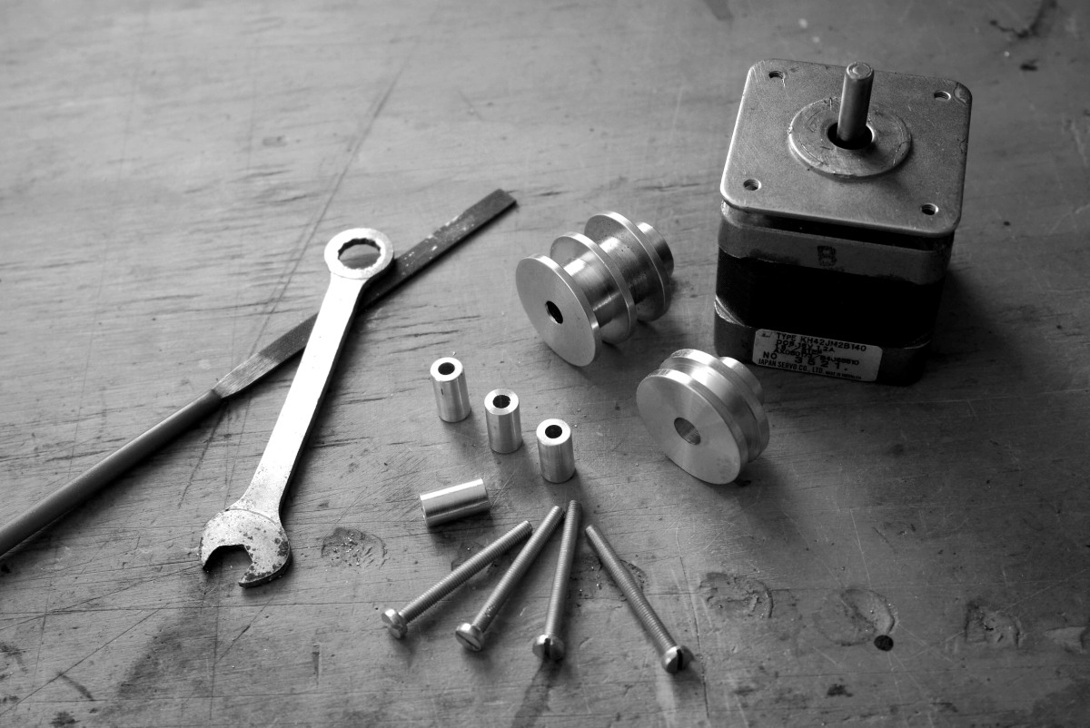
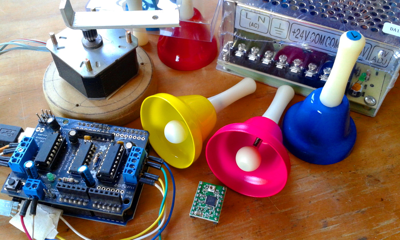
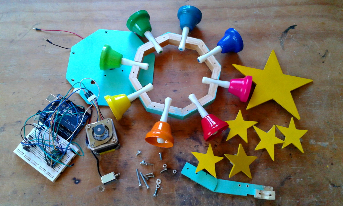
These are some of the components at the beginning of the project, some are going to be used some not.

This is my last project, a musical Christmas wreath controlled by a Arduino  microprocessor . I was looking for a Christmas project where I can use a recycled stepper motor. The idea came when I found a set of tuned bells in individual notes so I have this idea to use them as a Christmas wreath.

jinglebotoct

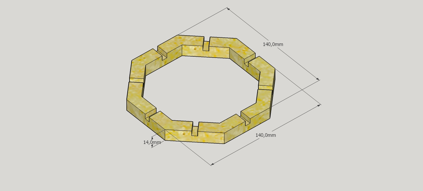
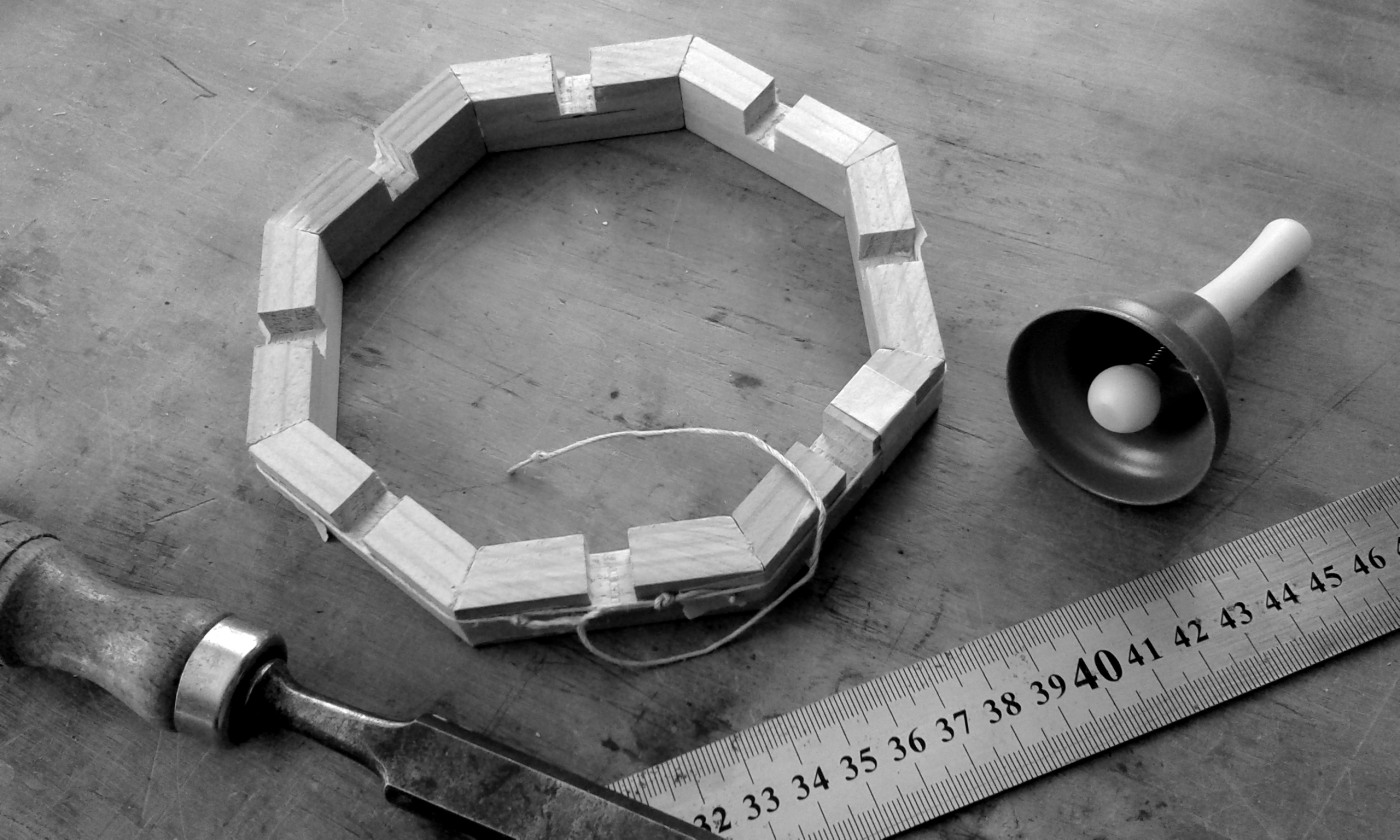
Wood Octagon 140 x 140 mm.

bellbot4

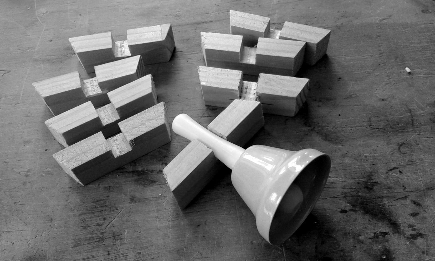
The eight segments cut and with a recess to hold the bells.

bellbot5

The pieces are glued and a piece of string keeps all together while it dries

bellbot6

On the wooden structure goes a piece of 3mm MDF and in the middle a Nema 17 stepper motor is fixed.

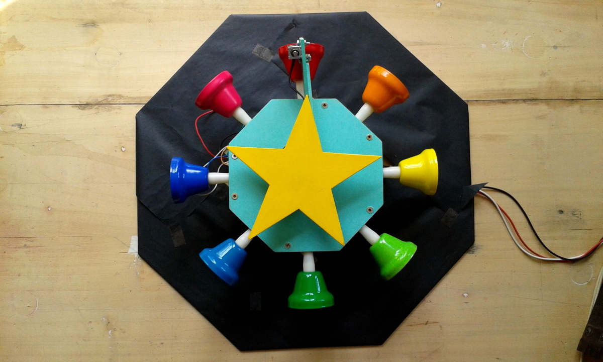
As the idea was to make a Christmas wreath the 8 bells are distributed in a circle on an octagonal base of 14 cm. wide, at each vertex of the octagon slot supports the bells. In the center of the octagon a stepper Motor Nema 17, recycled from a printer, is installed.

bellbot7

On the motor pulley a wooden support is made on which the arm is going to be fixed.

bellbot11

The components of the arm: A 8 gr microservo, the wooden support, 3 mm MDF arm, 3mm nuts and bolts.

bellbot12

The servo mounted ready for the first test.

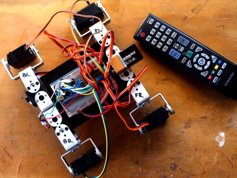
To adapt the engine I made a wooden support where goes an arm where an 8 gr microservo is attached. In the first version I used an Arduino UNO and an Adafruit motor shield.

In this video we see that the system works but the servo is too slow to hit the bell and the stepper motor is not strong enough and steps are skipped.

bellbot14

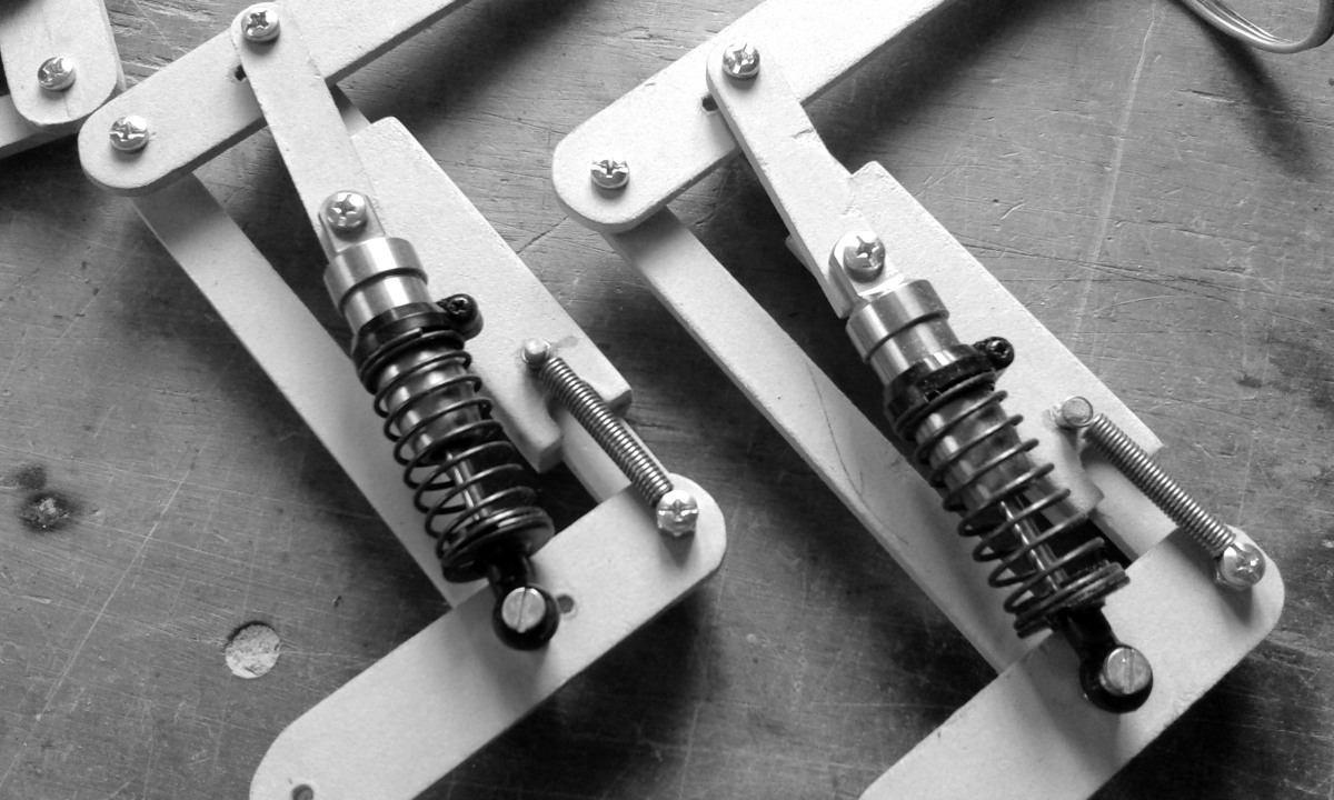
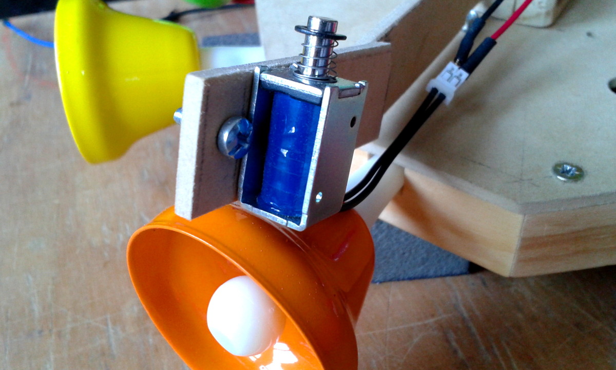
In the secónd test the servo is replaced by a 5 volt solenoid

bellbot15

The controller is now a A4988 stepper driver and BD677 transistor to control the solenoid.

In the second version I use a recycled Nema 17 from a Xerox copier and A4988 stepper driver to control the motor via the amperage and thus use a higher voltage. To hit the bells I use now a small 5 volt solenoid controlled by a digital signal through a BD677 transistor..

Now the engine has enough torque and no steps are skipped, the solenoid hits the bells properly. The problem that arises now is that the arm acts as a sounding board and amplifies the sound of the motor.

bellbot18

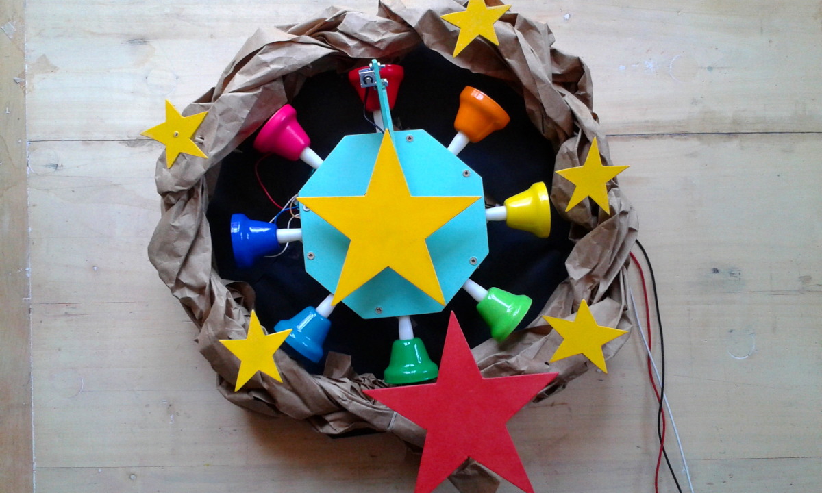
A little paint and some stars made of 3 mm MDF and everything is ready to be mounted.

bellbot21

The system is ready, mounted on a 3mm MDF base and the electronic components are under the structure.

bellbot19

The wreath is made with brown paper, the stars are installed and all is ready to run.

I made a new arm support polyethylene and the noise decreases slightly. Structure is now on wooden posts and is mounted on an octagonal 3 mm MDF base. From scrap wood I cut some stars, all items are painted. With brown  paper I make a braid and with it the wreath where the stars are installed and now all is ready to run.

I will leave it as it is because this project is very simple and only intended as an experiment to learn to use the stepper driver. If someone needs the code and the electronic scheme just ask.

Jingle-Bot

bellbot1

Estos son algunos de los componentes al inicio del proyecto, algunos se van a usar otros no.

Este es mi último proyecto, una corona de Navidad musical controlada por un microprocesador Arduino. Tenía la idea de hacer un proyecto navideño y aprovechar de utilizar unos motores paso a paso que estaba reciclando. El proyecto parte con un juego de campanas afinadas en notas individuales.

jinglebotoct

Octógono de madera de 140 x 140 mm.

bellbot4

Los ocho segmentos cortados y rebajados para sostener las campanas.

bellbot5

Las piezas están encoladas y un trozo de cordel sirve de prensa.

bellbot6

Sobre la estructura de madera va una pieza de MDF 3mm y en el centro se fija un motor paso a paso Nema 17.

Como la idea era hacer una corona navideña las 8 campanas se distribuyen en circulo en una base octogonal de 14 cm. de ancho, en cada vértice del octógono una ranura soporta las campanas, en el centro de este octógono se instala un motor paso a paso Nema 17 reciclado de una impresora.

bellbot7

Sobre la polea del motor se hace una abrazadera de madera en la que se fijará el brazo.

bellbot11

Los componentes del brazo: Un microservo de 8 gr. la abrazadera de madera, el brazo de MDF 3 mm y tornillos y tuercas de 3 mm.

bellbot12

El servo montado listo para la primera prueba.

Hice una abrazadera de madera donde va un brazo que integra un mini servo de 8 gr. En la primera versión usé un Arduino UNO y un motorshield de Adafruit.

En este video se ve que el sistema funciona pero el servo es muy lento para golpear la campana y el motor paso a paso no tiene suficiente fuerza y se salta pasos.

bellbot14

En el segundo sistema se reemplaza el servo por un solenoide de 5 volts.

bellbot15

El controlador ahora es un driver A4988 y un transistor BD677 para controlar el solenoide.

En la segunda versión uso un motor Nema 17 reciclado de una fotocopiadora Xerox y un driver A4988 para poder controlar el motor mediante el amperaje y de esa manera usar un voltaje mayor. Para golpear la campana uso un pequeño solenoide de 5 volts controlado por una señal digital a través de un transistor BD677.

Ahora el motor tiene el torque suficiente y no se salta pasos, el solenoide golpea las campanas adecuadamente. El problema que aparece ahora es que el brazo actúa de caja de resonancia y amplifica el ruido del motor.

bellbot18

Un poco de pintura y unas estrellas con restos de MDF 3 mm y todo está listo para armarse.

bellbot21

El sistema está armado, se monta en una base de MDF 3mm y la parte electrónica queda bajo la estructura.

bellbot19

Con papel kraft se hace la corona, se instalan las estrellas y está listo para funcionar.

Hice una nueva abrazadera de polietileno y el ruido disminuye un poco. La estructura va sobre unos postes de madera y todo se monta en una base octogonal de MDF 3mm. De restos de madera se cortan unas estrellas, se pintan todos los elementos. Con papel kraft hago una trenza y con ella se hace la corona donde se instalan las estrellas.

Lo voy a dejar así ya que este proyecto es muy sencillo y solo pretende ser un experimento para aprender a usar el stepper driver. Si alguien necesita el esquema electrónico o el código solo pregunte y lo publico.

Walker-Bot 1

OLYMPUS DIGITAL CAMERA
Este es un robot que no estaba en mis planes construir, no tenía pensado hacer un robot caminante pero la ver otro proyecto y tener disponibles servos robóticos hice el intento y este es el primer resultado.
This is a robot that was not in my plans to build, I did not plan to make a walking robot but after seeing another project and having robotic servos available I did ​​the attempt and this is the first result.

OLYMPUS DIGITAL CAMERA

Solo tuve que hacer una pieza de aluminio ya que los servos tenían sus propios soportes. Usé cinco servos de 15kg de torque más otros servos normales por lo que no es simétrico pero para estas primeras pruebas todo funcionó.
I just had to make a piece of aluminum as the servos had their own brackets. I used five 15kg servos plus other normal so it is not symmetrical but for these first tests everything worked.

OLYMPUS DIGITAL CAMERA

El manejo es por intermedio de un control remoto infrarojo de televisor y el control es por medio de un Arduino Nano.
Operation is via an infrared TV remote and the control is by an Arduino Nano.

OLYMPUS DIGITAL CAMERA
Este es un video del robot caminando, tuve que usar una fuente de poder externa porque el consumo de los servos de 15kg es alto.
This is a video of the robot walking, I had to use an external power source because the 15kg servos have a high amperage rate.

Hacker-Bot Sumo

Este es un video de las primeras pruebas del Hacker-Bot Sumo. El código necesita bastante depuración y es más difícil de lo que pensé, hay muchos sensores que tienen que estar funcionando al mismo tiempo y no se pueden usar delays que dejan los sensores ciegos por un rato. La aproximación debe ser completamente distinta, tengo que estudiar el asunto.

This is a video of the first test of the Sumo-Bot Hacker. The code requires a lot of debugging and is more harder than I thought, there are many sensors that must be running at the same time and can not use delays that leave the blind sensors for a while. The approach should be entirely different, I have to study the matter.