Este proyecto es la copia de otro que vi en youtube, El original está hecho en aluminio para un rifle AR15, como yo no tengo armas reales ni tengo intención de tenerlas lo hice en MDF para una pistola de aire comprimido, la cosa era probar que lo podía hacer. El diseño es mi variante y la programación también. La torreta es guiada automáticamente por colores gracias a una cámara Pixy CMUCam5 que es capaz de seguir hasta 10 colores distintos que se programan. La gracia es que el programa está en la cámara por lo que funciona sin computador y se conecta a un arduino Nano para controlar los motores paso a paso. Al igual que el proyecto original no dispara automáticamente. Próximo paso usar una cámara que detecte movimiento y claro.. dominar el mundo…
This project is a copy of another that I found on youtube, The Original is made of aluminum for an AR15 rifle, as I have no actual weapons or intend to have them I made it in MDF for an airgun, the thing was to prove that I could do it. This is my own design and programming. The turret is guided by colors automatically with a camera Pixy CMUCam5 camera that Is able to track up to 10 colors that are programmed. The program is in the camera so it works without a computer and connects to an Arduino Nano to controlling stepper motors. Like the original project it does not fire automatically. Next step is use a camera with motion detection.
Este es el último proyecto en el que he estado trabajando un slider para la nueva cámara que compré.
This is the last project I’ve been working a slider for the new camera I bought.
El slider está hecho de tubos de aluminio, madera terciada y unas poleas torneadas en polietileno montadas en rodamientos.
The slider is made of aluminum tubes, plywood and polyethylene turned pulleys mounted on bearings.
Las poleas están hecha en polietileno de alta densidad HDPE. The pulleys are made in high density polyethylene HDPE.
Luego las poleas se montan sobre rodamientos de 22mm de diámetro. Then the pulleys are mounted on bearings 22 mm in diameter.
Hice una herramienta especial para tornear la ranura de las poleas. I made a special tool for turning the pulley Groove. Las piezas de terciado fueron cortadas en el router CNC que hice yo mismo. The pieces of plywood were cut in the CNC router I made myself.
Las piezas de terciado listas para ser pegadas.
The plywood pieces ready to be glued.
Los soportes terminales están listos. The terminal supports are ready.
El slider se mueve impulsado por un motor paso a paso Nema17 controlado por un Arduino Nano y un driver A4988. The slider moves driven by a Nema17 stepper motor controlled by anArduinoNanoandA4988driver.
El soporte de la cámara está hecho momentáneamente en MDF, una vez que funcione lo voy a rehacer en aluminio. The camera stand is made momentarily in MDF, once it work I’ll redo it in aluminum.
Hice una polea en aluminio y un tambor para hacer una especie de huinche. I made an aluminum pulley and a drum to make a kind of winch.
Este es un video de la primera prueba del slider, hay bastantes cosas que arreglar pero básicamente ya funciona.
This is a video of the first test of the slider, there are many things to fix but basically it Works.
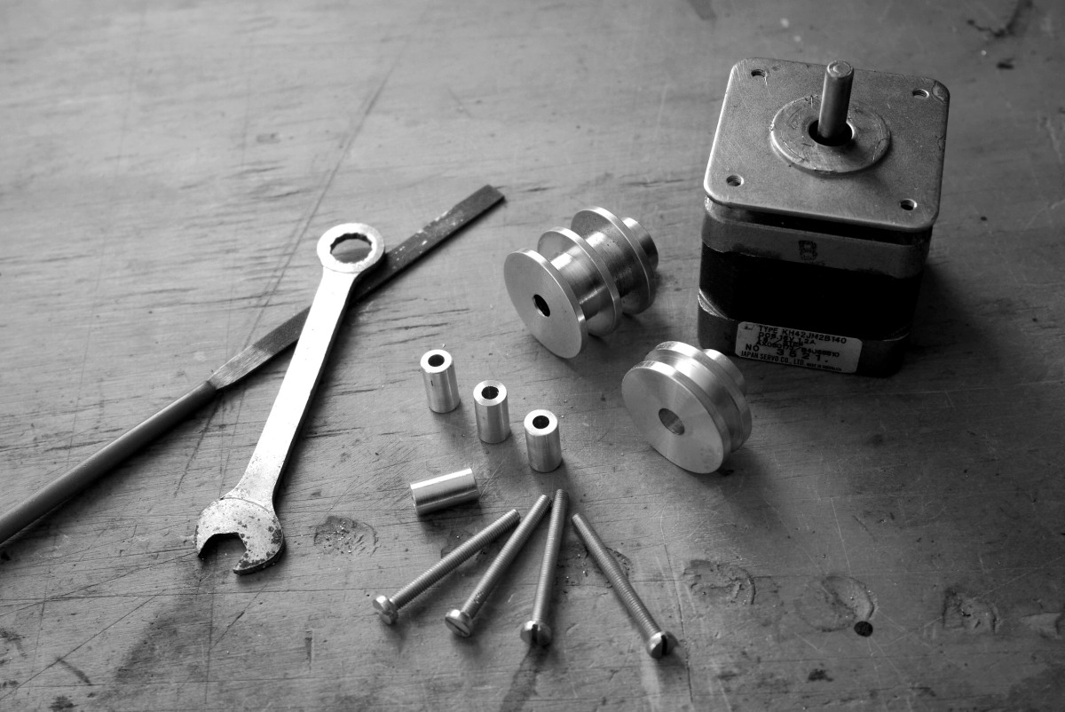
These are some of the components at the beginning of the project, some are going to be used some not.
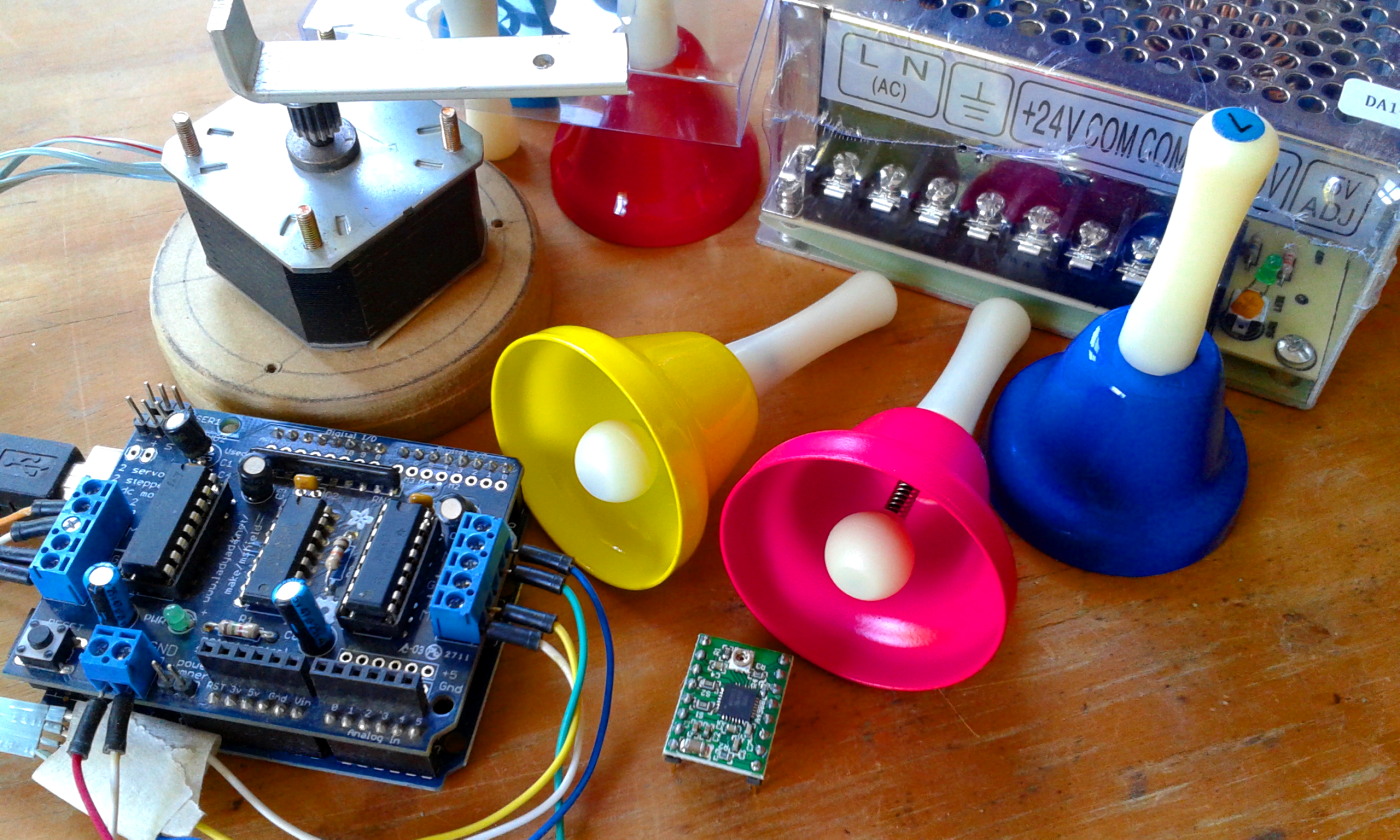
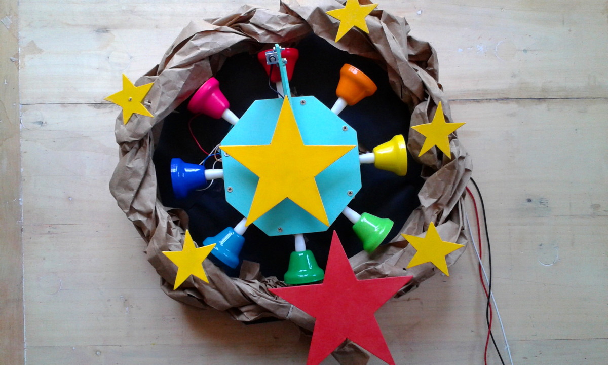
This is my last project, a musical Christmas wreath controlled by a Arduino microprocessor . I was looking for a Christmas project where I can use a recycled stepper motor. The idea came when I found a set of tuned bells in individual notes so I have this idea to use them as a Christmas wreath.
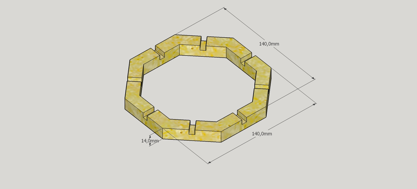
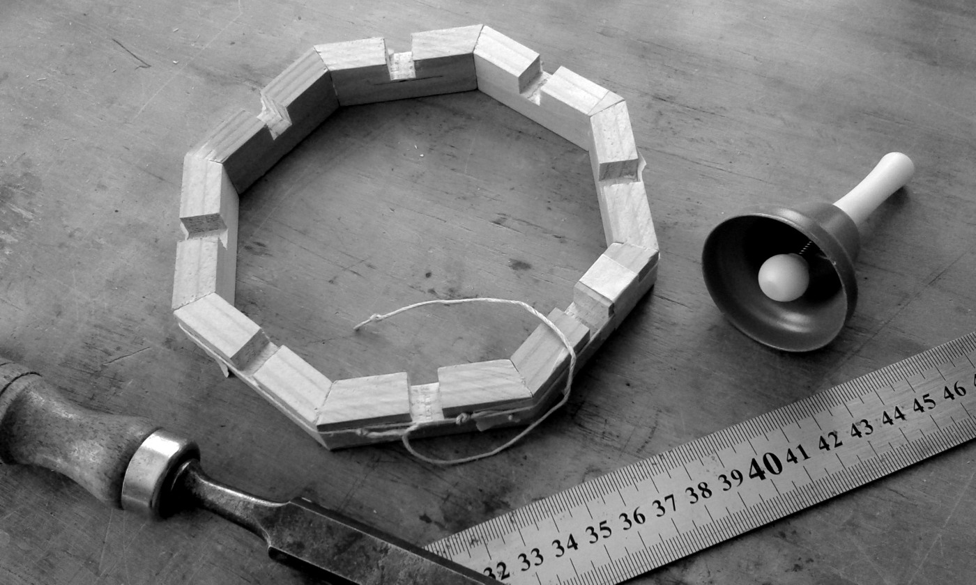
Wood Octagon 140 x 140 mm.
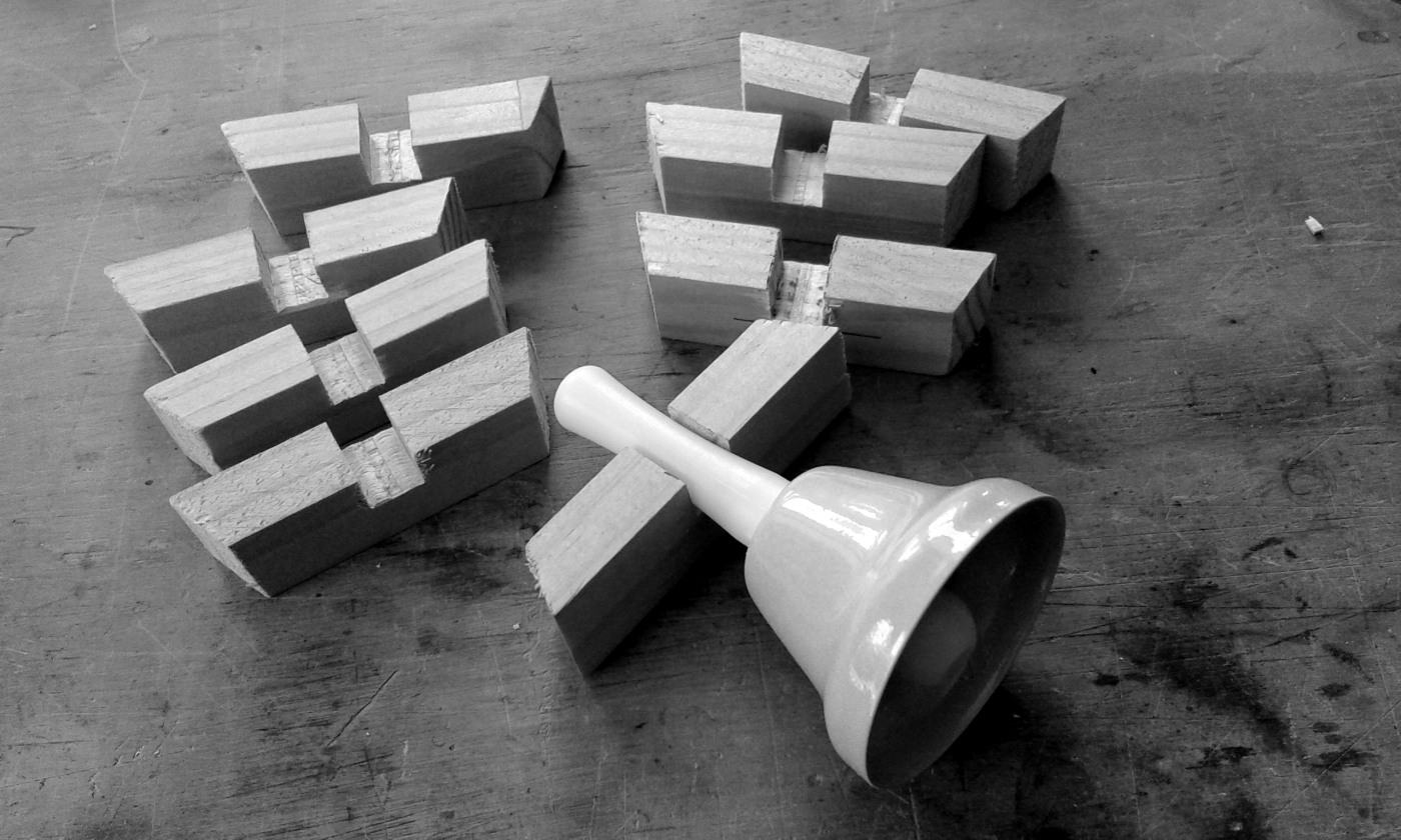
The eight segments cut and with a recess to hold the bells.
The pieces are glued and a piece of string keeps all together while it dries
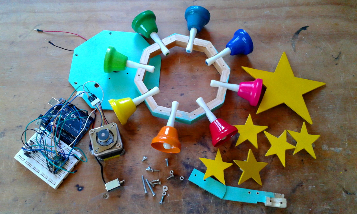
On the wooden structure goes a piece of 3mm MDF and in the middle a Nema 17 stepper motor is fixed.
As the idea was to make a Christmas wreath the 8 bells are distributed in a circle on an octagonal base of 14 cm. wide, at each vertex of the octagon slot supports the bells. In the center of the octagon a stepper Motor Nema 17, recycled from a printer, is installed.
On the motor pulley a wooden support is made on which the arm is going to be fixed.
The components of the arm: A 8 gr microservo, the wooden support, 3 mm MDF arm, 3mm nuts and bolts.
The servo mounted ready for the first test.
To adapt the engine I made a wooden support where goes an arm where an 8 gr microservo is attached. In the first version I used an Arduino UNO and an Adafruit motor shield.
In this video we see that the system works but the servo is too slow to hit the bell and the stepper motor is not strong enough and steps are skipped.
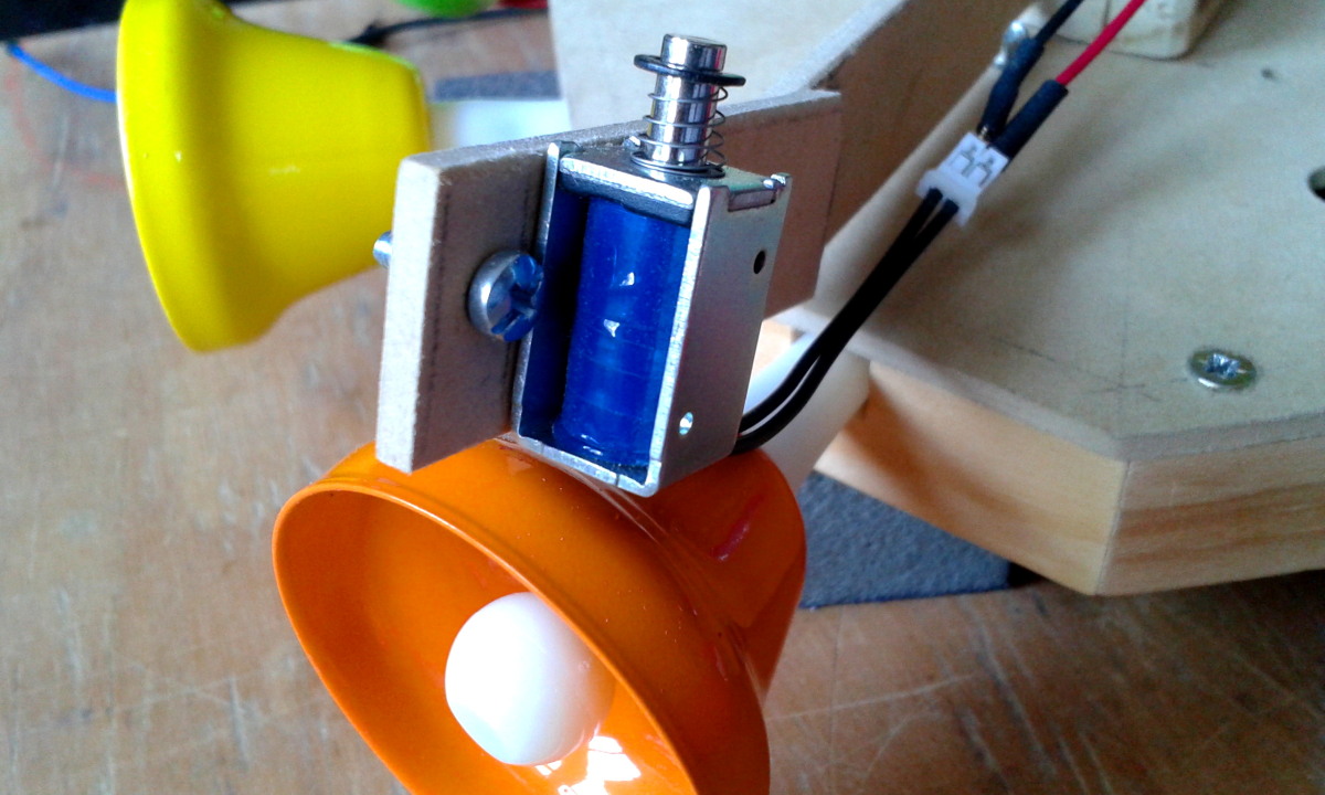
In the secónd test the servo is replaced by a 5 volt solenoid
The controller is now a A4988 stepper driver and BD677 transistor to control the solenoid.
In the second version I use a recycled Nema 17 from a Xerox copier and A4988 stepper driver to control the motor via the amperage and thus use a higher voltage. To hit the bells I use now a small 5 volt solenoid controlled by a digital signal through a BD677 transistor..
Now the engine has enough torque and no steps are skipped, the solenoid hits the bells properly. The problem that arises now is that the arm acts as a sounding board and amplifies the sound of the motor.
A little paint and some stars made of 3 mm MDF and everything is ready to be mounted.
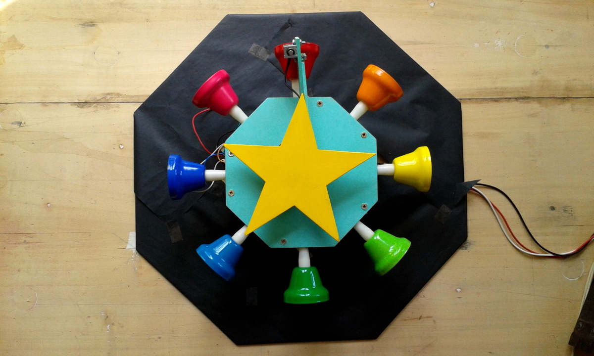
The system is ready, mounted on a 3mm MDF base and the electronic components are under the structure.
The wreath is made with brown paper, the stars are installed and all is ready to run.
I made a new arm support polyethylene and the noise decreases slightly. Structure is now on wooden posts and is mounted on an octagonal 3 mm MDF base. From scrap wood I cut some stars, all items are painted. With brown paper I make a braid and with it the wreath where the stars are installed and now all is ready to run.
I will leave it as it is because this project is very simple and only intended as an experiment to learn to use the stepper driver. If someone needs the code and the electronic scheme just ask.


 Las piezas de terciado listas para ser pegadas.